Mobile, continuous corrugation measuring system
Simple but simply perfect: the RMF 2.3E with its patented measuring principle for detecting irregularities of the rail length profile.
Corrugation in wavelenghts from 10 to 3000 mm are digitally measured and recorded related to the covered distance. The data capture is completely automatic and continuos for both rails simultaneuosly.
Whether before or after grinding/milling/welding – RMF provides real raw data from the rail surface. Never before corrugation measuring was so quick and precise.
- reliable and accurate – Electronic digital measuring. Measuring sensors with 1/100 resolution.
- efficient and intelligent – Only 1 person needed for operation. Simulaneous measuring of left + right rail.
- precise and visible – Automatic data capture every 2 mm. Real time monitoring of all values.
- suitable for vignole and grooved rails (option: adaption kit for grooved rails available)
- suitable for both, gauge 1435 and 1000 mm (other gauges on request)
In Practice
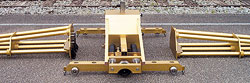
Initial build-up
The 5-piece measuring device is mounted on-site and put on the track. Assembling and preparation for operation is finished within 5 minutes while no additional tools are required.
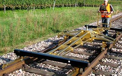
Data capture
The data recording works continuously through the measuring pins in relation to the covered distance. Thereby the surface of the left and right rail are simultaneously recorded under control of the RMFcatcher operation software.
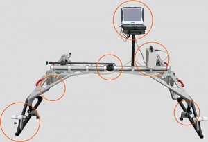
The particular measurement values are digitally scanned and transferred to the MPC notebook for final saving. The MPC is mounted on the RMF device and shows all incoming measurement values in real time (resolution: 1/100 mm).
Measuring principle
The leading and trailing faces of each side work as a rolling straight edge, that is pulled along the rails. A sensor placed centrally at the level of the straight edge, tracks the surface oscillations and passes the corresponding X and Y coordinates to the computer.
Data analyses
After the measuring process is finished, the captured raw data can be reviewed and analysed on-site. The raw data represents the scanned longitudinal profile of the rails. In the raw data display, all wavelenghts are superimposed.
The results can be digitally filtered and split into waves of favoured lenghts by use of software “MultiViewer” or “Ril824-Viewer”. In addition to this graphic analyses, the measurement files can be exported into other softwares (i.e. Excel), too.
Technical Data
| Effective ranges | for vignole rail |
| for track gauge 1000 mm | 985 – 1035 mm |
| for track gauge 1435 mm | 1420 – 1470 mm |
| Chord length | 2200 mm |
| Measured wavelengths (min./max.) | 10 mm / 3000 mm |
| Measuring range of sensors | -3,5 to +2,5 mm |
| Distance measurement | 2,0 mm |
| Accuracy | 0,01 mm |
| Adjustable rail beds | flexible |
Evaluation software
For the analysis, the raw data are digitally filtered and split into waves of favoured lengths. Therefore, the filter ranges indicated right are available:
10 – 30 mm
30 – 100 mm
30 – 300 mm
100 – 300 mm
300 – 1000 mm
1000 – 3000 mm
Dimension and weight
|
Length x Width x Height (built-up) |
2200 x 1680 x 780 mm |
| Length x Width x Height (in transport case) | 2280 x 550 x 420 mm |
| Weight | 45 kg |
Special features
The device is length and cross insulated. Software and measuring device are officiall approved by DB AG.
Note : RMF 2.3E is available for other track gauges and can be prepared for use on grooved rails, too (= option).